Modding: Putting an ATX system into a Apple PowerMac G5 Case - Mark II
So, after I was happy with the concept in the Mark I version, in 2011 I decided to go a further in my goal to do a good G5 casemod. The original G5 Mac used watercooling for its dual powerPC processors, and while the air cooled setup worked, as I pushed the limits (especially with GPU programming) I started having issues with high temperatures and noise. So I decided to attempt to go with liquid cooling for the "Mark II" of this project.
Goals
- I am still trying to keeep the outside as authentic as possible
- More refinement
- Better/quieter cooling. I upgraded the GPU to a GTX250, which was (a) quite a bit noisier, and (b) hitting temperatures >100C when running at sustained full load, which I was uncomfortable with. So I decided to do liquid cooling, to keep the temps down, without resorting to lots of noisy fans.
First stage: Relocating the PSU
There were two reasons to relocate the PSU:
- I needed more power for the upgraded GPU, and all the PSUs with enough power were full size rather than Micro, making it difficult to fit in the bottom of the case
- If I am to utilise liquid cooling, I have to move the PSU to be above everything else. The reason for this is simple, the "non conductive PC coolant" you can buy is non-conductive only for low voltages used in computer systems. At 240V AC it is conductive and any leaks would be very dangerous. By moving the PSU to be above everything, any leaks will just drip down, and worst case scenario will leak out of the holes at the bottom of the case, not reaching any of the high voltage sections.
In order to fit the PSU above everything, I need to put it on the top shelf. To do that, I have to cut a hole in the shelf for airflow (as the PSU fan points downwards):
1. We marked out where the PSU will fit, with a rough estimate of the hole for the fan
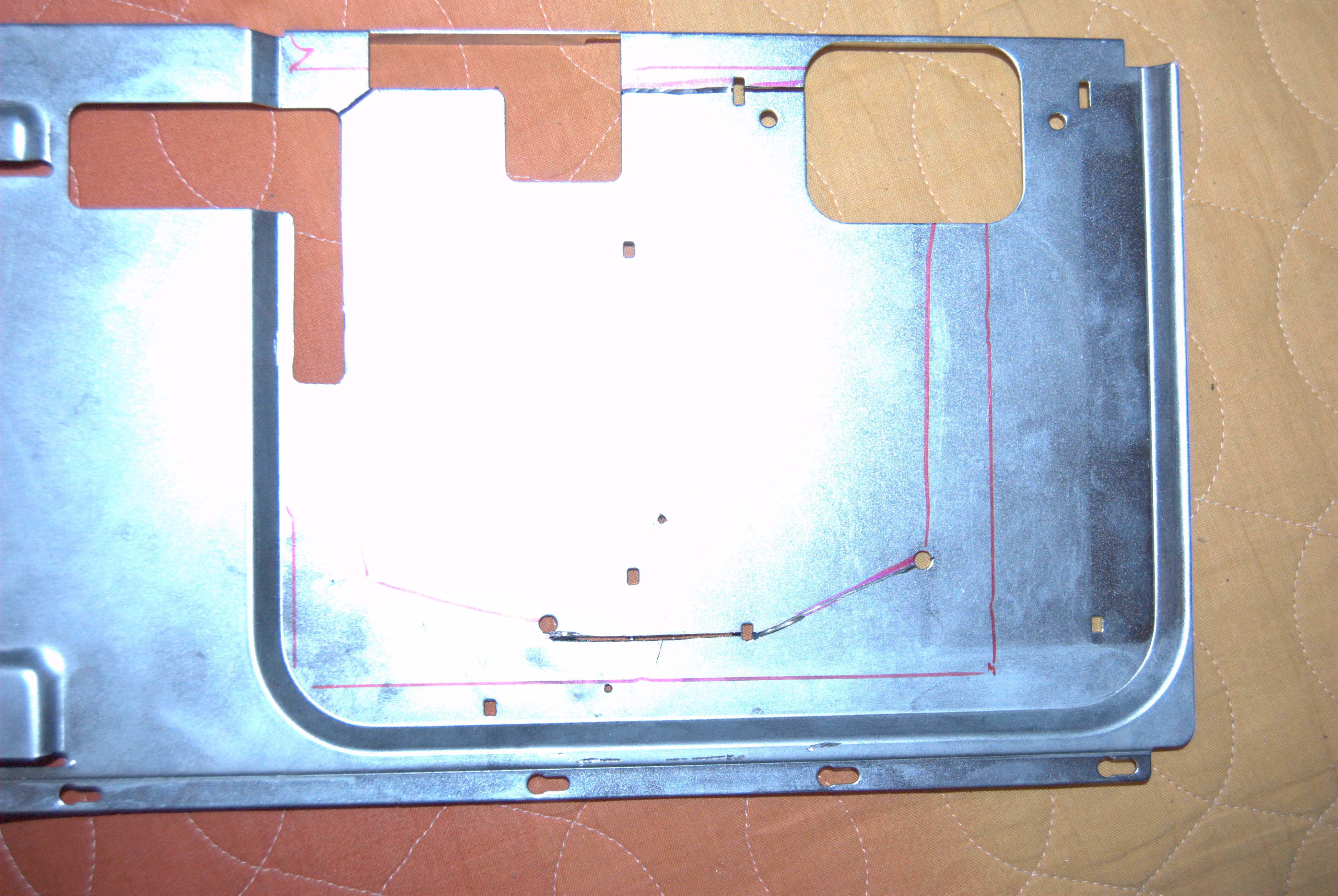
2. Using the Dremel, I rough cut the sections needed
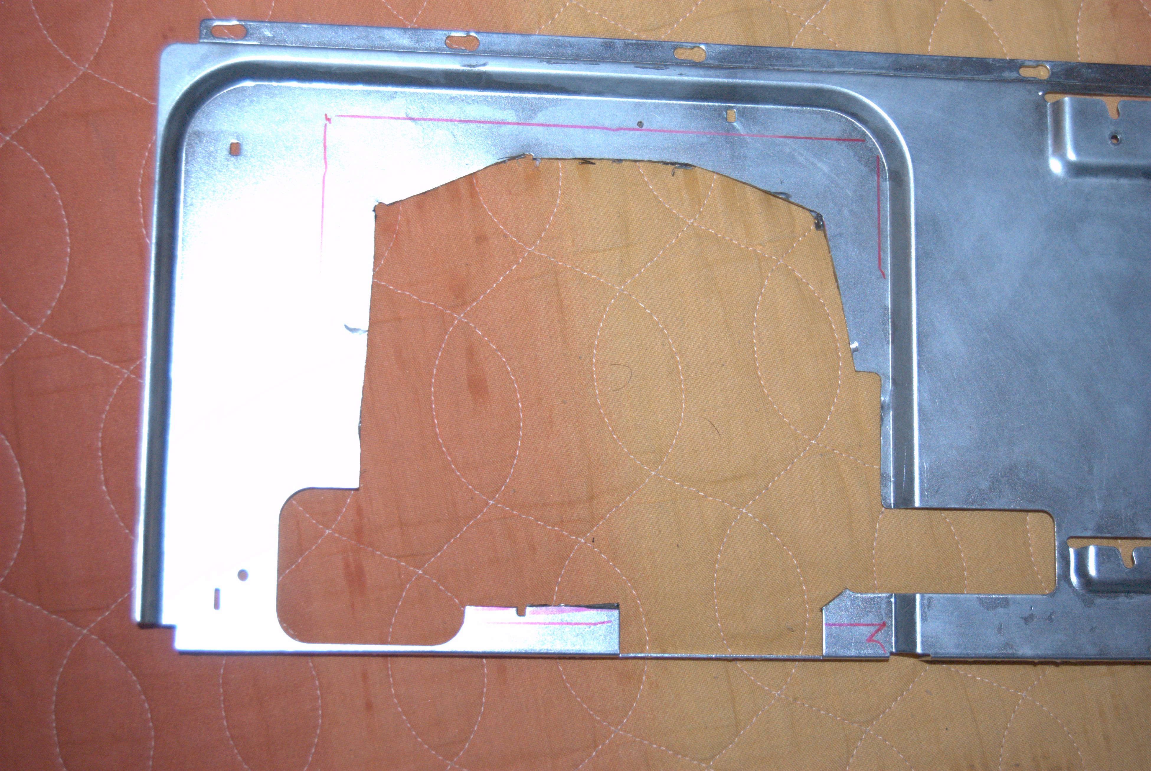
3. Bit of smoothing and fettling with a test fit, and the PSU is in place!
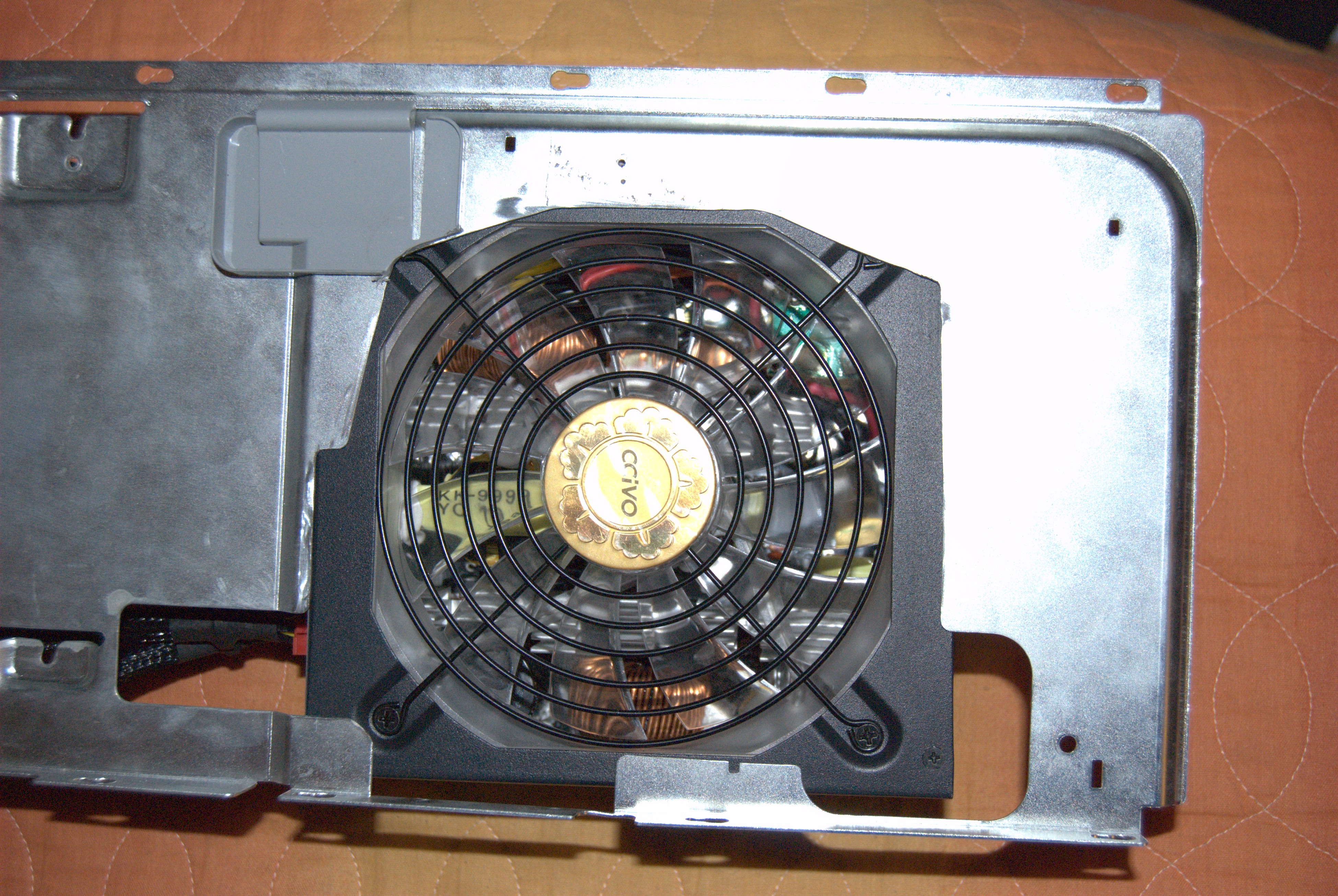
4. Test fit the PSU and shelf in the case
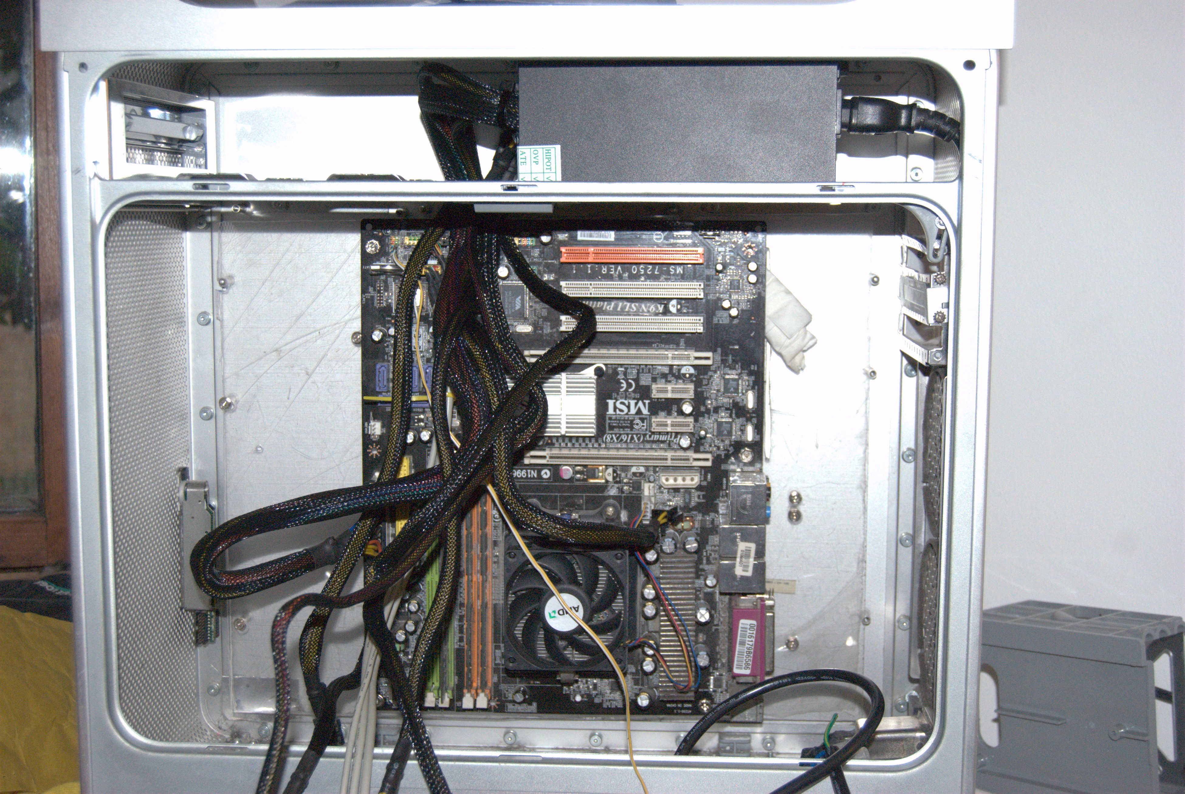
With the PSU relocated,I made an extension cord between the lower socket, and the new PSU location. The original power socket was a good 4cm above the floor of the case and there were loads of holes below it, so I was not worried about leaks causing any problems. I also made a new "full length" PCI bracket (out of old card/wood composite from a box file of all things). Being full length it was a lot more sturdy than the old plexiglass setup, which was prone to bending and by the end of it had cracked. Here is the current state, wired up with all the PCI cards for testing:
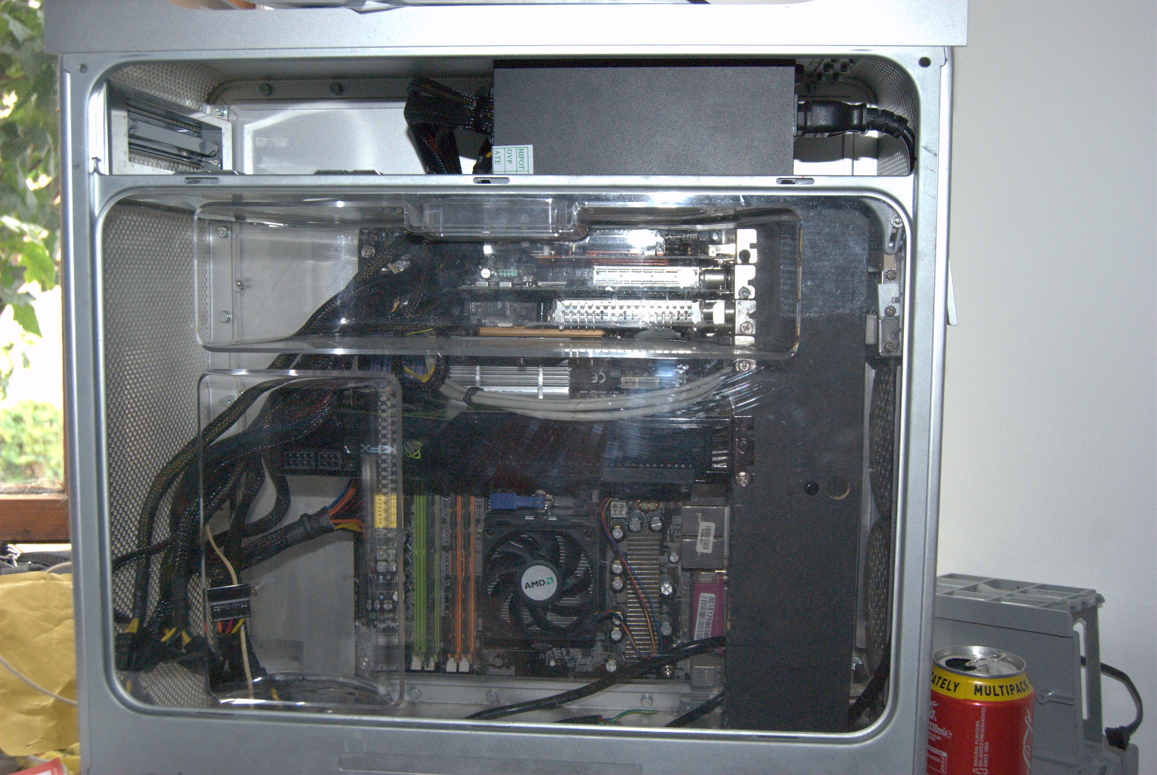
So far so good!
Second stage: Designing the liquid cooling setup
Initial design
The plan was to get a radiator that could fit the entire front of the case, maximising the amount of heat we can transfer. However the "Liquid cooling" components for PCs seemed overly expensive for what they are, and none of the radiators I could find were the right size. Thinking I can do liquid cooling on a budget, I decided to design and build my own system from scratch.
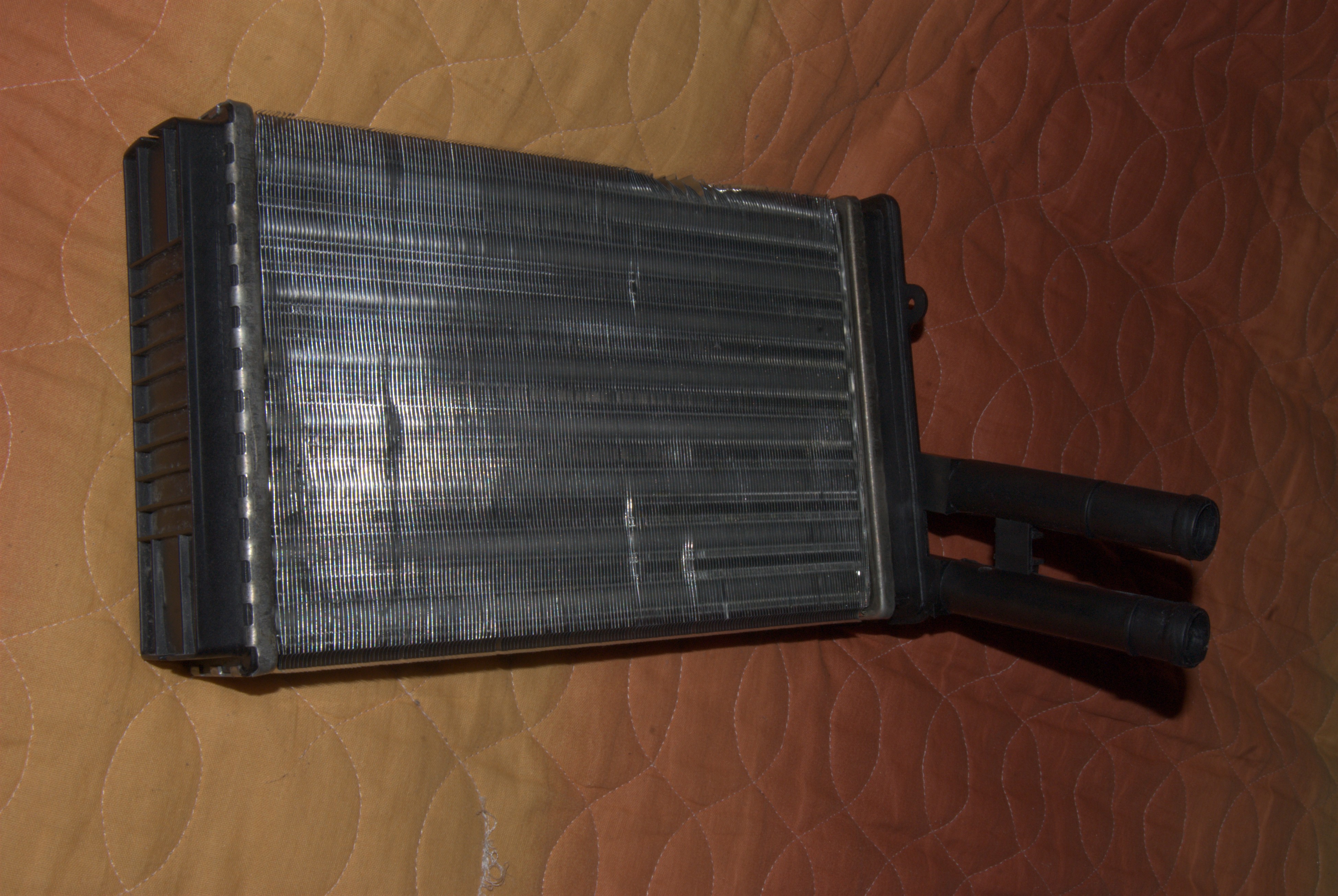
First thing I had to do is find a radiator that fits the case. I want something that fills the entire front of the case. There is a lot of scope for airflow and I want to make use of it. After a lot of research, I found that the best fit I could find is a heater core from an Audi A4. These are small radiators that sit inside the dashboard and heat the air in the cabin.
So I purchased a heater core unit from an Audi A4, off ebay for around £10 - a few dings but no leaks. Being designed to exchange loads of heat in a small package, it is both thick (at 5cm thickness) and full of fine fins.
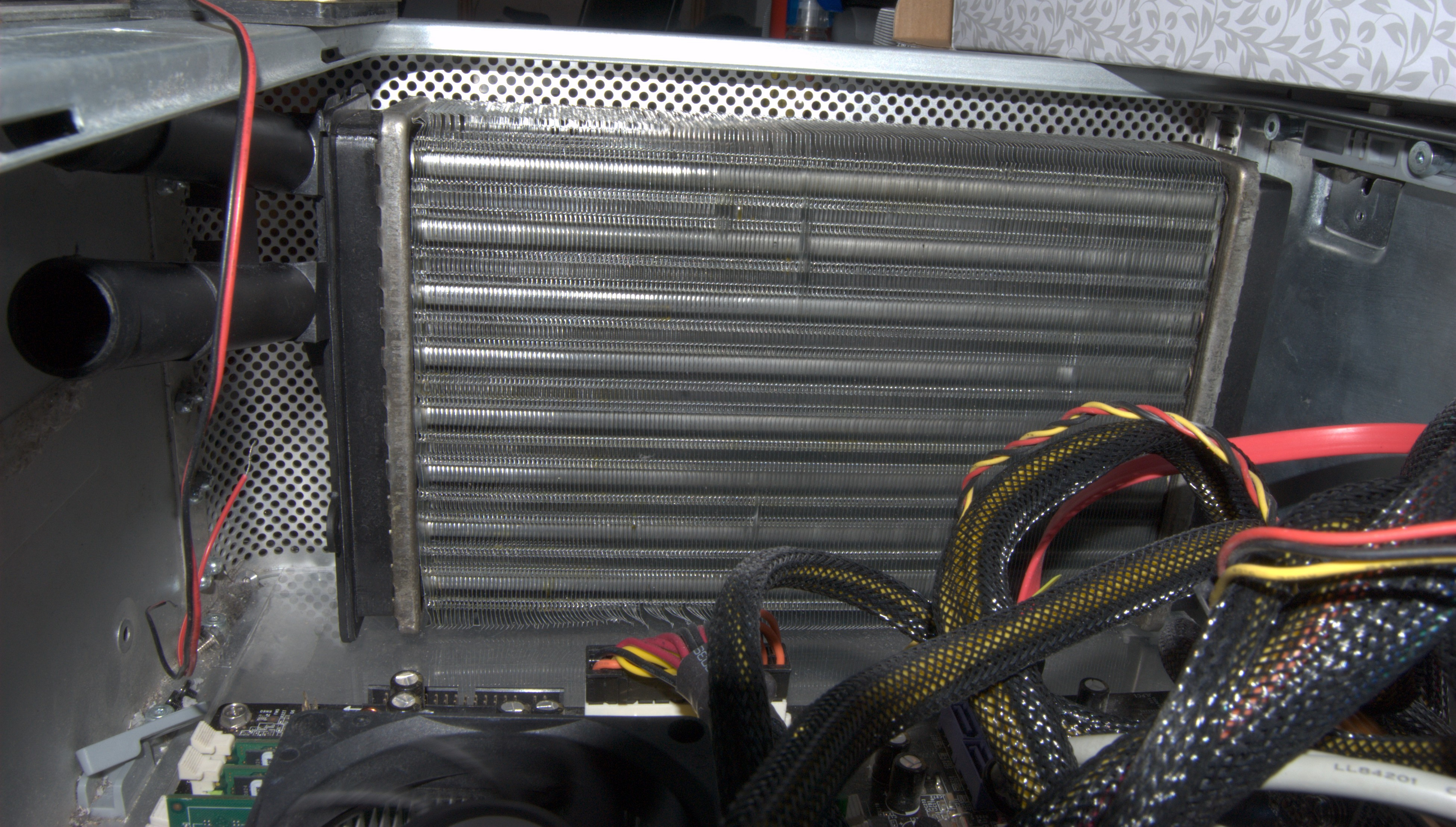
Test fitting. Looks good so far:
There is enough space at the bottom for the pipework, and just enough space at the top to get a finger in to position the radiator.
However the radiator will not sit stable as is, because its base it not flat, it has the pipes at the bottom and coming ot at an angle. As we are aiming to not change the exterior, just screwing the radiator to the front of the case is not acceptable. Hence the decision to design a mount for it.
Radiator mount
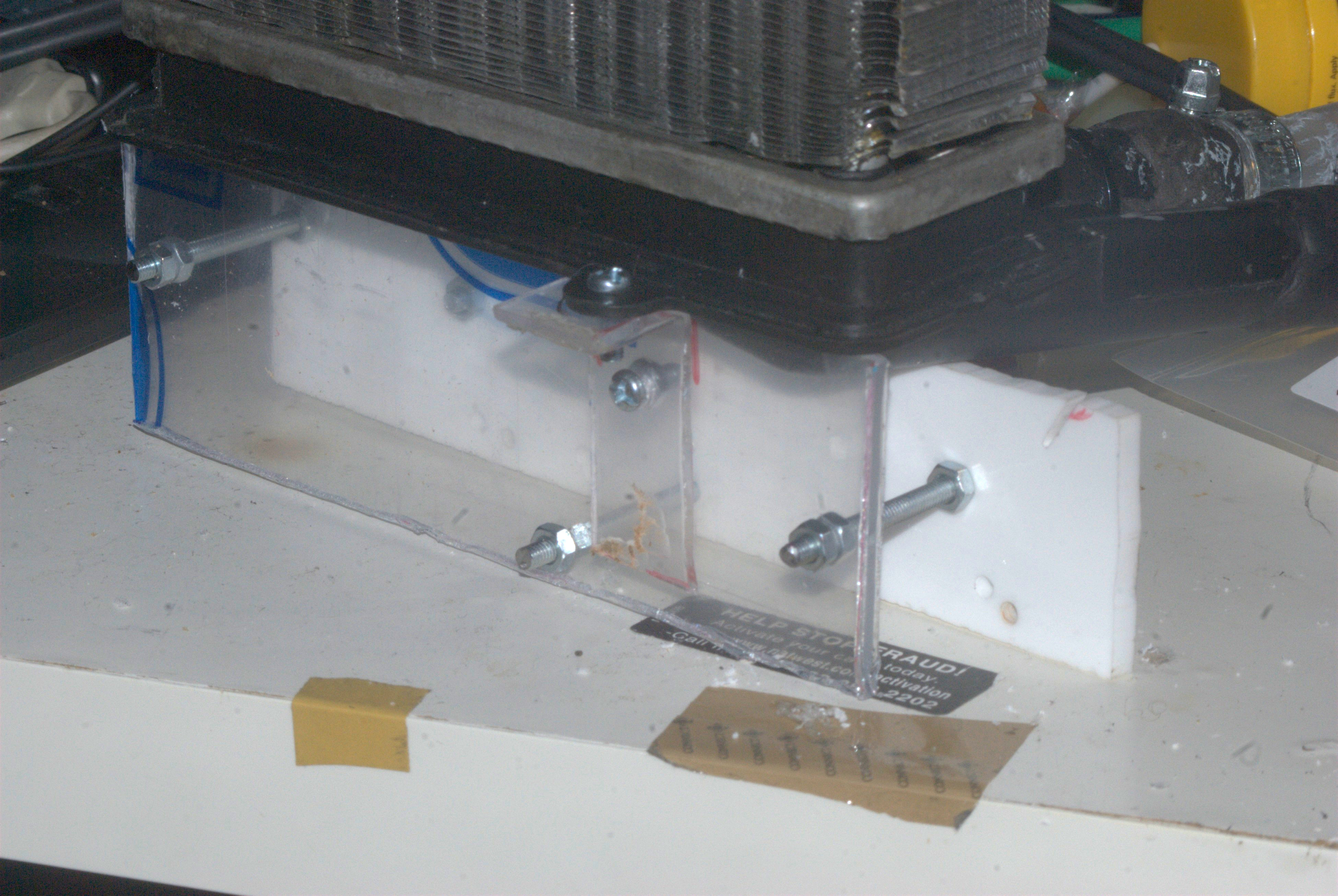
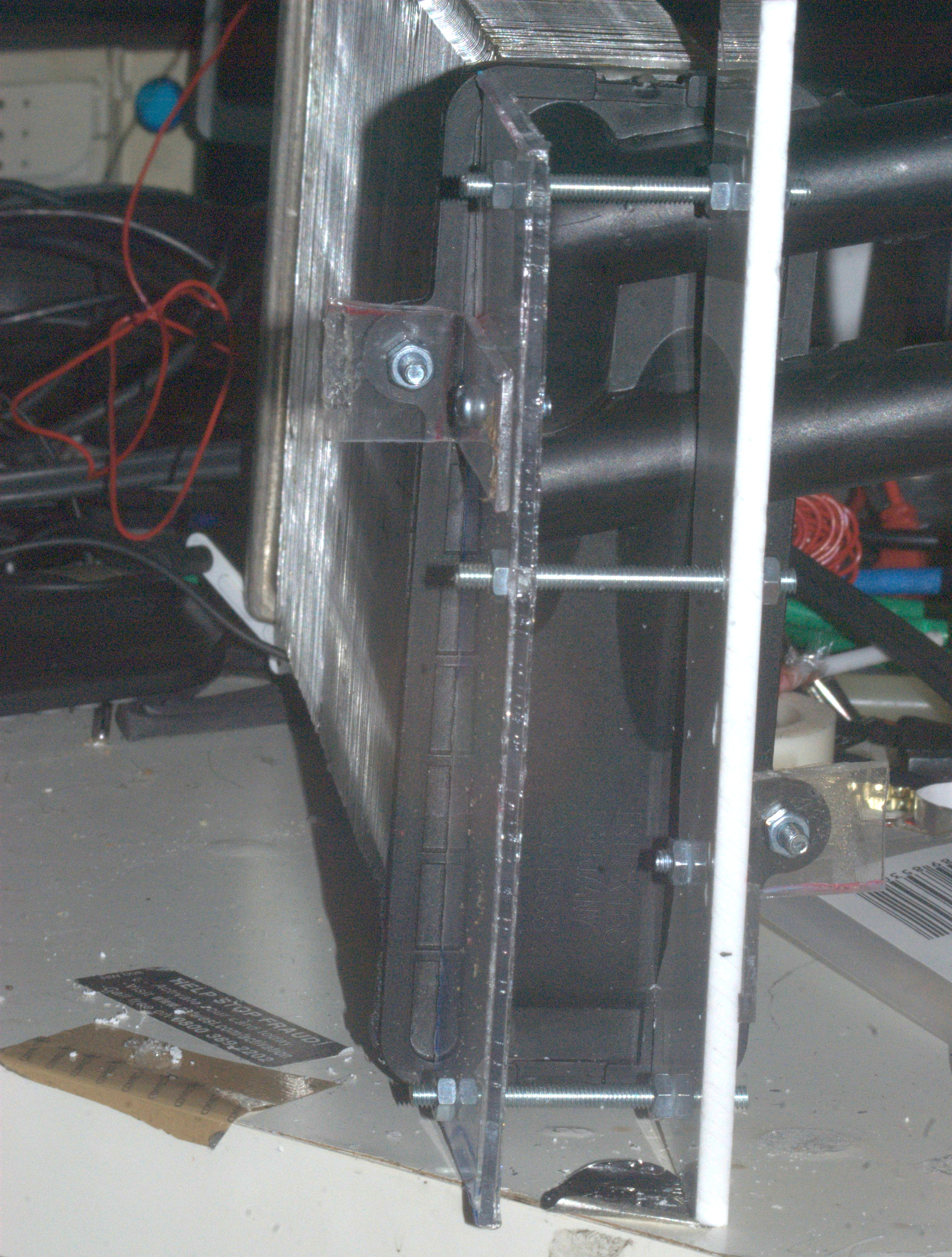
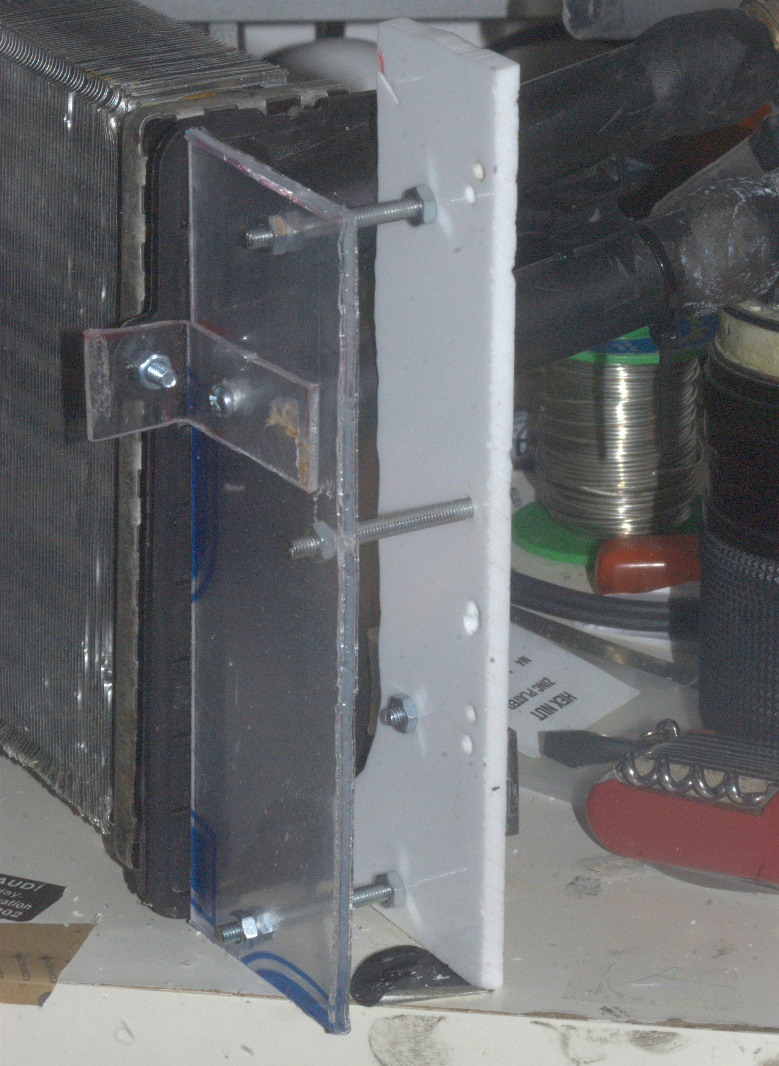
A mount was traced out on cardboard, then cut out and offered up to the radiator. We had to clear the pipes, but still provide a level and stable base where the radiator can rest. After some trial and error, a working mount was devised, and then the pattern was transferred to acrylic and cut out. The result is a two-piece mount that screws to the existing mounting holes at the bottom of the radiator, as shown:
In order to be able to use the radiator with the rest of the system, I needed to fit barbs on it, which I did as follows:
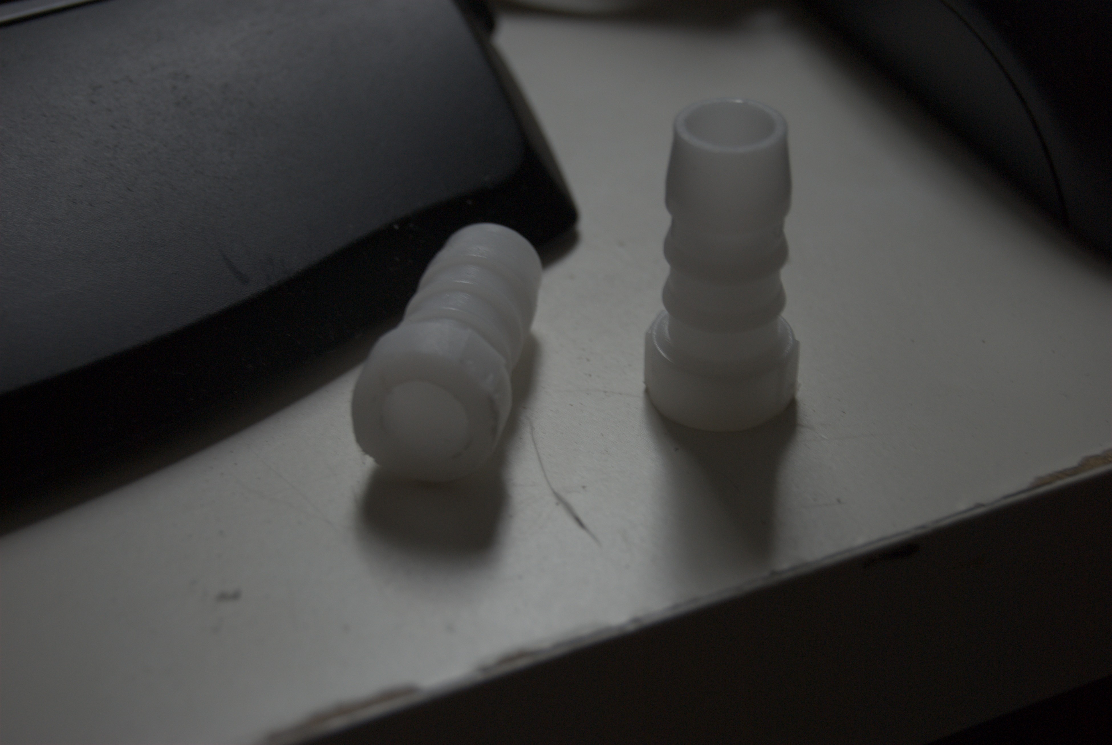
1. I bought some of these mating connectors, to connect two pipes together
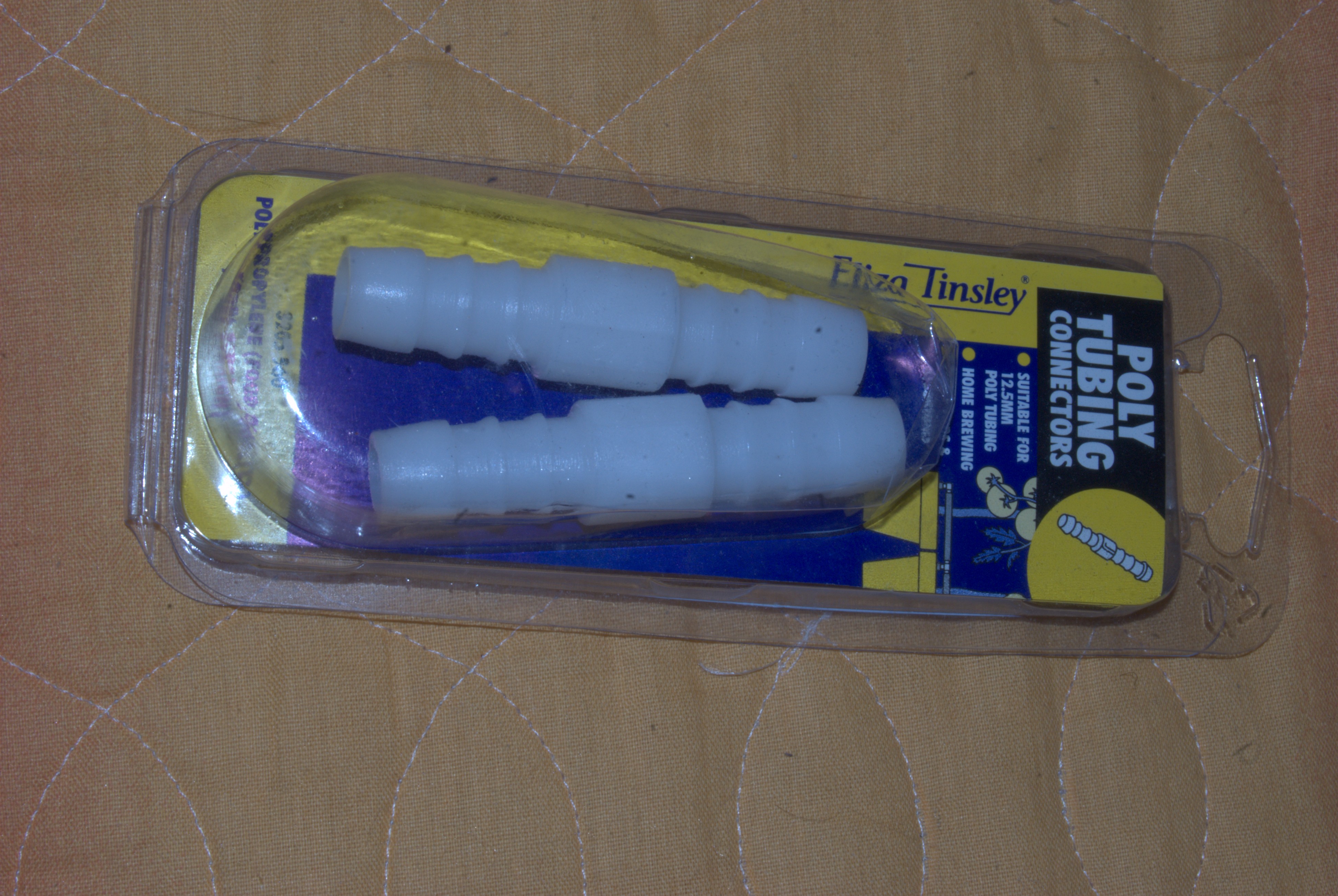
2. One connector was sawn in half, giving us two pieces, one for each port on the radiator.
3. The two halves were mated to the radiator by friction fit. I used a heat gun to melt the radiator pipes a bit, so as to bind to the barb connectors well. This worked, but it seems the plastic was treated with some flame retardent chemicals, because it stank horribly (I would not do it again).
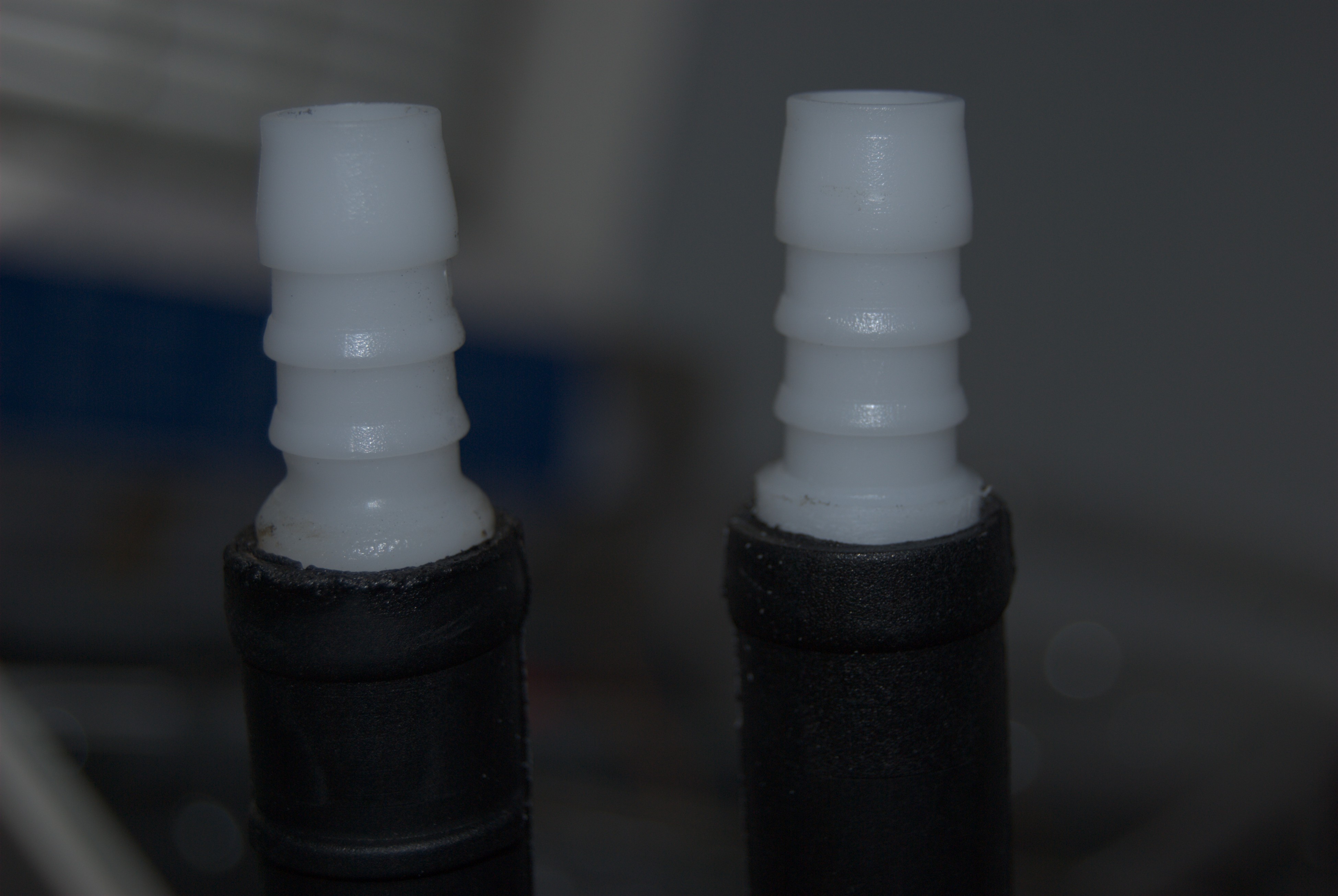
4. Once cooled down, I wrapped them in epoxy putty, to guarantee a watertight seal
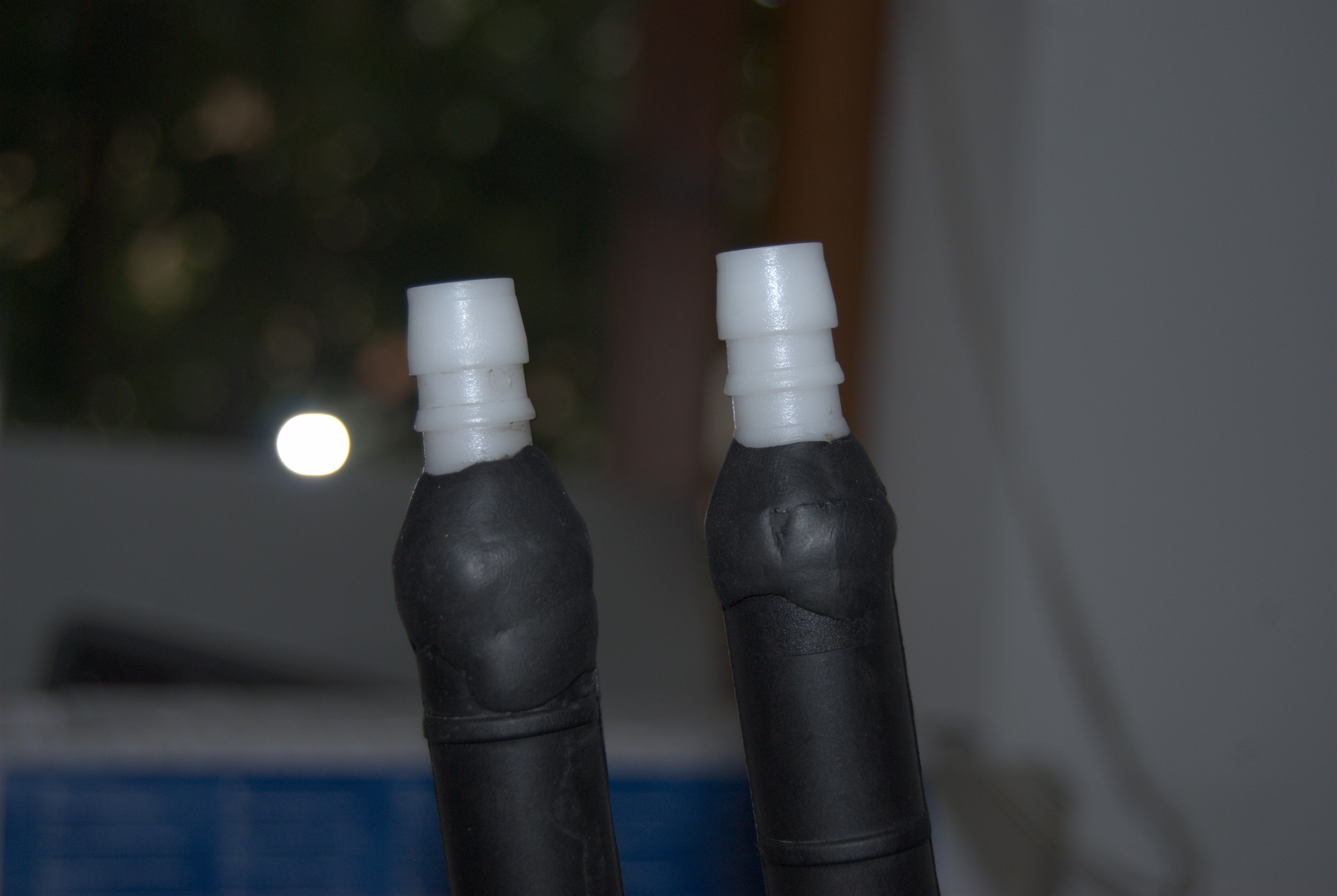
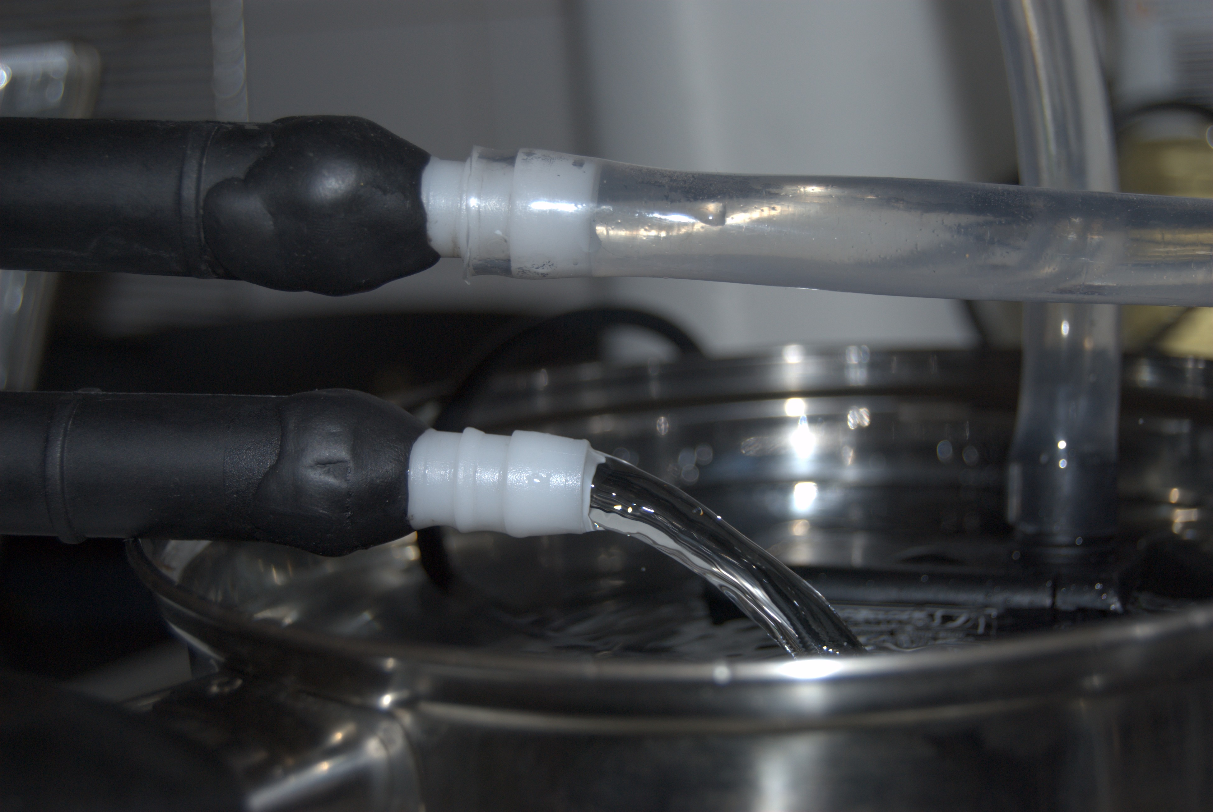
5. In order to confirm a watertight seal, I ran a test with plain tap water, including sealing the outlet port and letting pressure build in the radiator and connectors. No leaks encountered!
With that, we have the potential to build the system. I made the following diagram illustrating the system design:
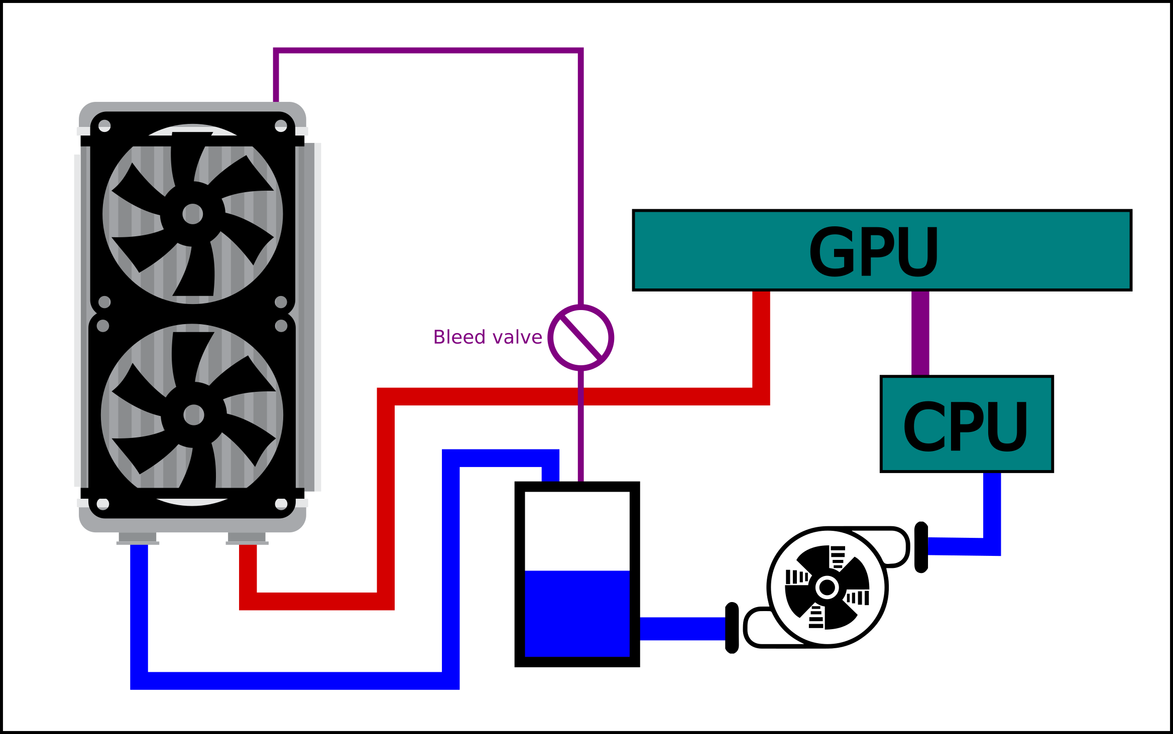
If we start from the coolant tank, the water goes to the pump (so that it only has to deal with the coolest liquid in the system), which then goes to the CPU first, which warms it up a bit, and the GPU, who's heat output is much larger. The hot coolant goes straight to the radiator, where it is cooled and returned to the tank, and the cycle continues.
We wanted the inlet and outlet pipes at the bottom, again so any leaks just harmlessly drip only the case floor rather than any electrics. The problem here is that it makes the top of the radiator the highest point in the system. As air bubbles will congregate at the highest point in the system, in this design that would be the top end of the radiator. Left unchecked the air pocket will expand and reduce the amount of heat that can be radiated causing the system to overheat. As such we have the bleed line and the "Bleed valve", so that air bubbles can escape the radiator and be returned to the tank.
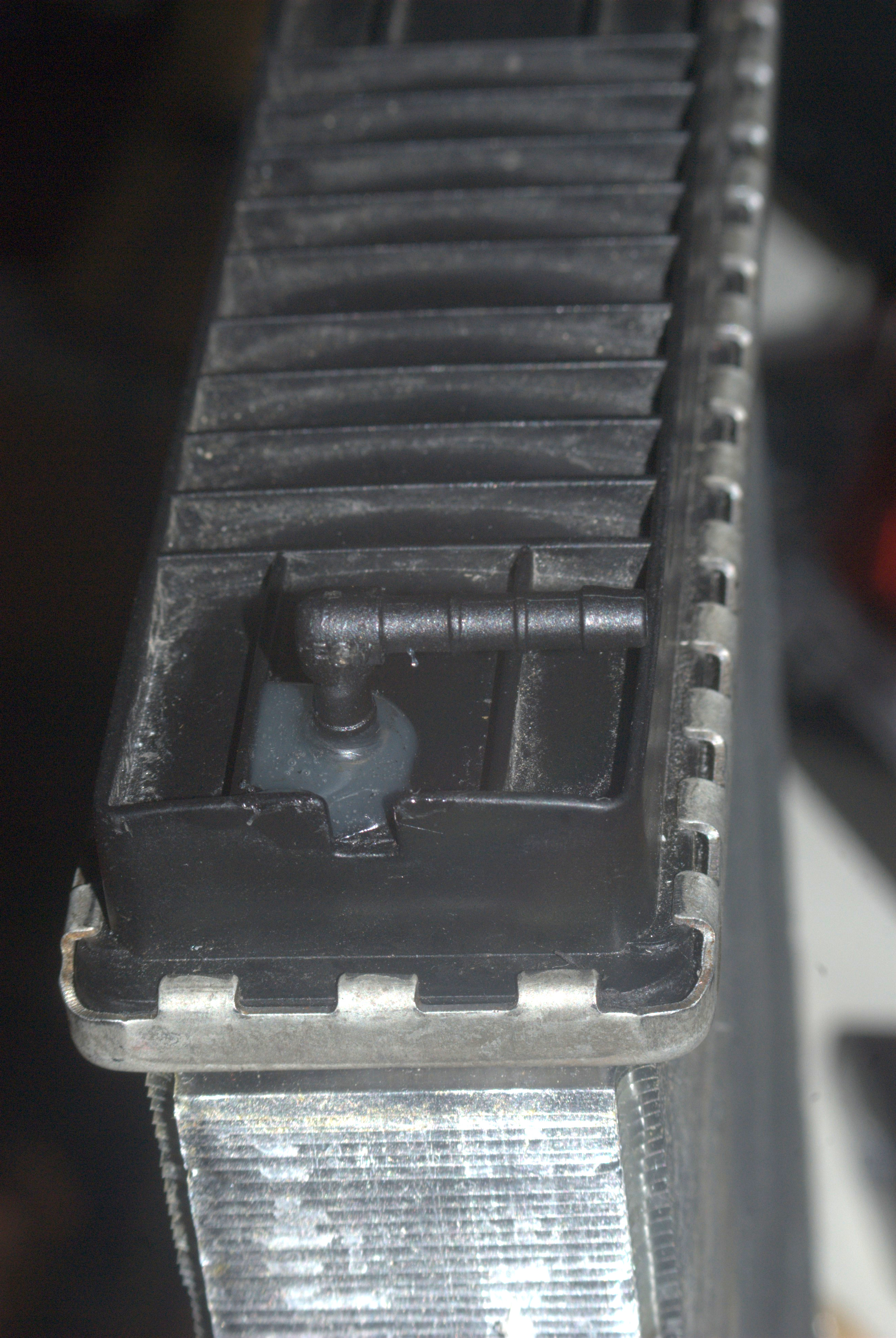
To achieve this. I drilled a small hole at the top of the radiator, and hot-glued in a 3mm 90° barb connector. As this is mostly to bleed air, we don't need a large diameter pipe (any coolant that flows through this end does not get properly cooled, so we want to keep it to a minimum).
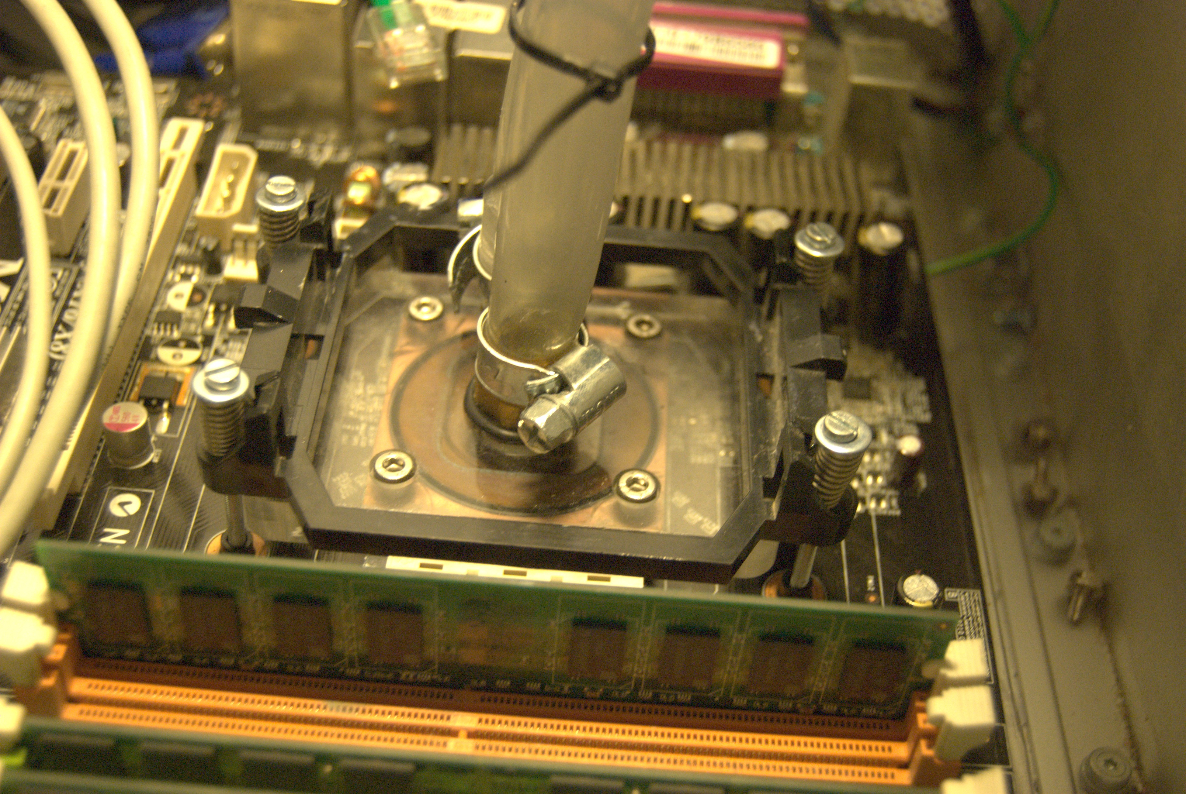
Once I settled on the design, the next thing I had to do was to get water blocks for the CPU and GPU. Rather than fashion my own (which I don't have the skills or tools to do), I decided to buy some second hand:
The waterblock did not fit my motherboard exactly, so I had to modify the original AMD CPU heatsink retainer to act as a flange to press down the waterblock. IMO it actually looks good, like its supposed to fit that way. I had to use longer screws, with springs to provide even tension across all 4 points of the retainer
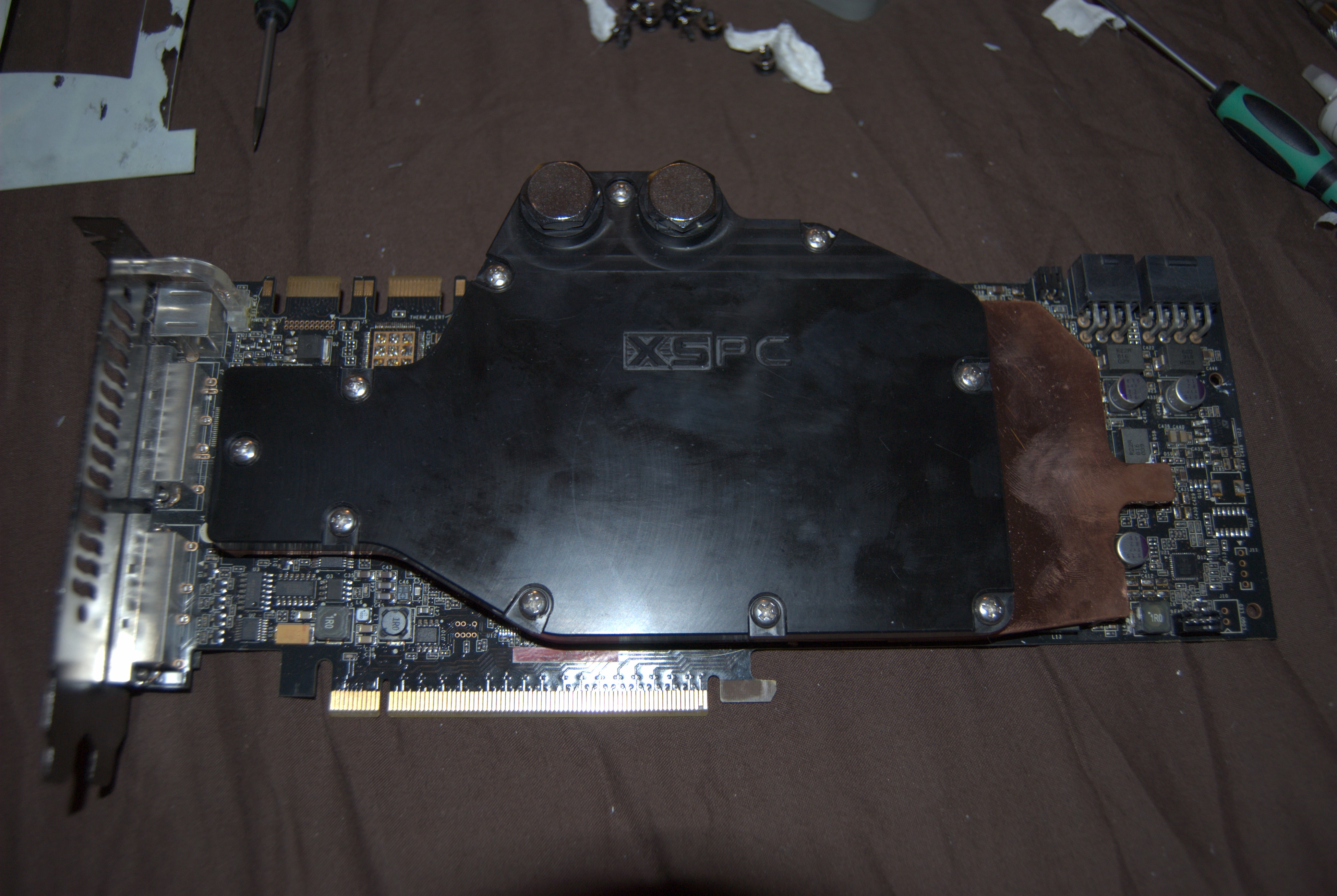
The GPU was much simpler. I just bought a proper waterblock that fits. The GPU produces so much heat and is so expensive that risking failure due to a badly fitting waterblock did not seem wise.
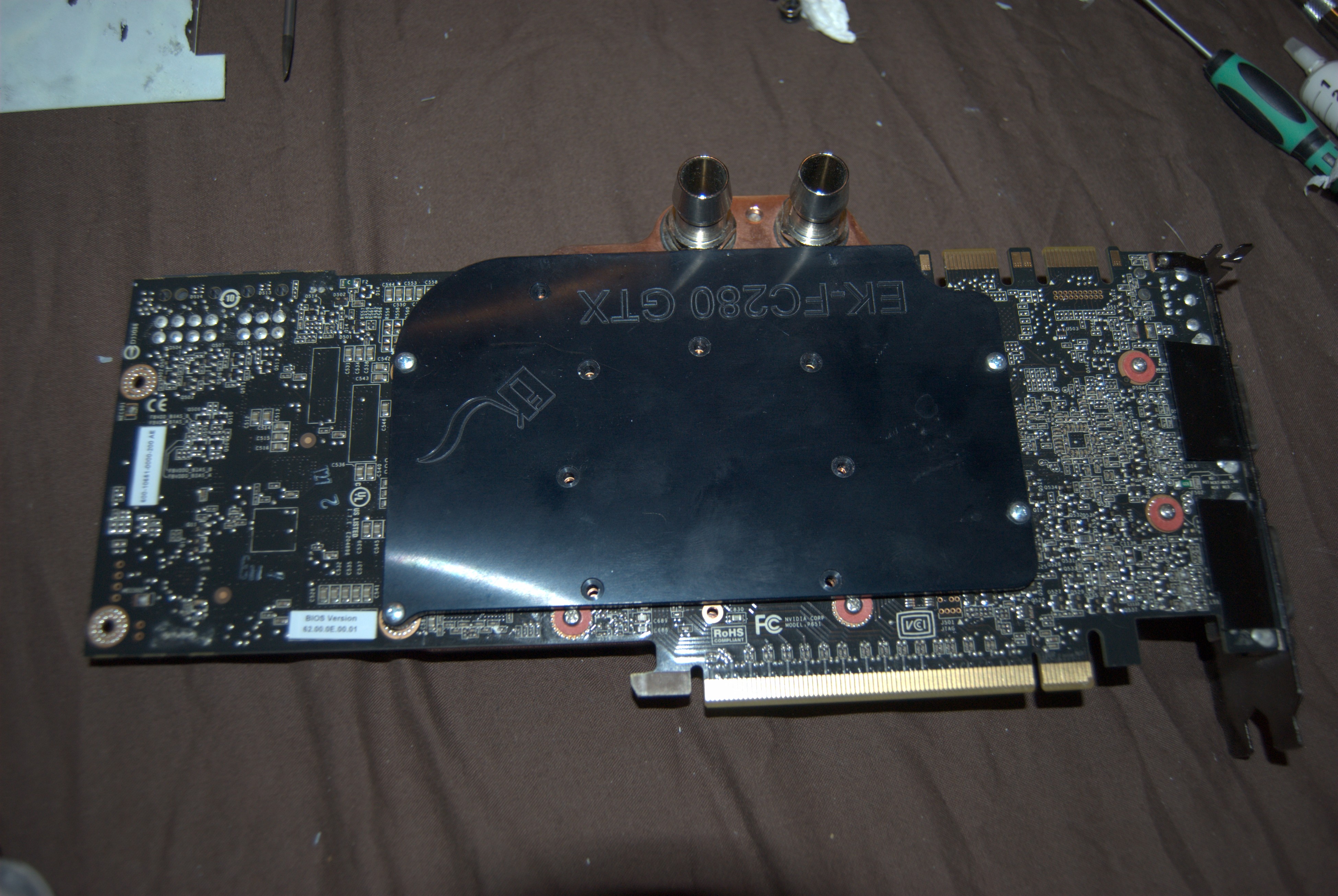
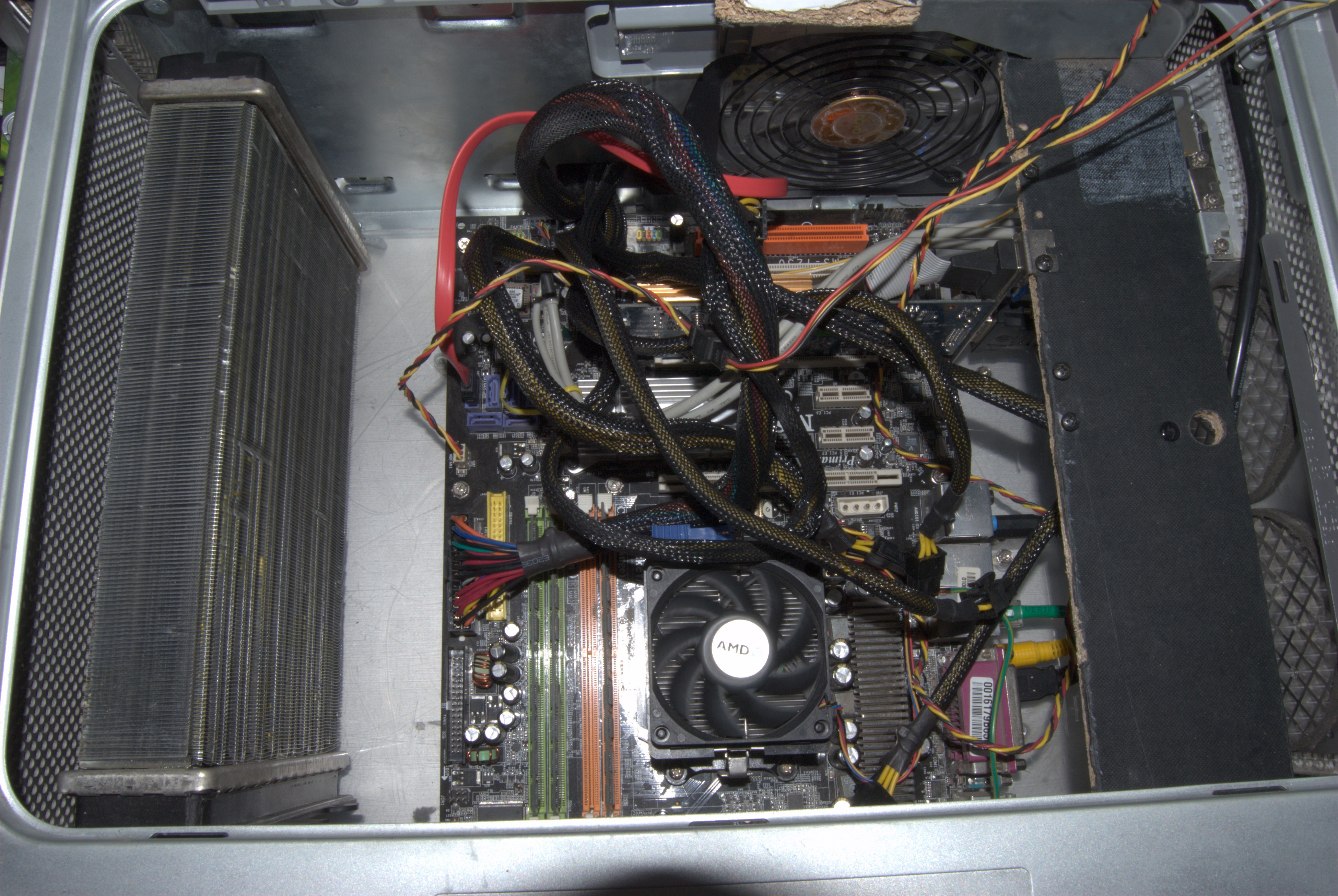
And with that, we can install the CPU and GPU into the case as shown:
We temporarily hooked it up with some silicone pipe and a half cut open water bottle as a resevoir. This was to test to make sure there were no leaks and that everything was working as expected. The pump is a standard 240V sealed aquarium pump that I got off ebay, and it does the job just fine. It is also quite quiet, all you really hear is a low rumble as it seems to spin at some low frequency (50Hz would be my guess, or a multiple). And here it is all powered up and alive!
We put a small fan in there just to get some basic heat exchange going, but it was all working well. The only thing that bugged me was the kink from the CPU and GPU block. It didn't leak, but I doubt it did the flow any good. After many attempts I just could not get it to not kink. Something about the pipe structure prevented it from cleanly turning at that radius. However it seems to be working ok for the moment, at least until I find some better piping.
Fourth stage: The front Panel
I wanted the front panel to work as much as possible as the original. The pins on the front panel are very closely spaced, which I found out is the same pin spacing as laptop IDE connectors. Having an old 2.5" IDE cable, I cut the connector down to size and mapped the front panel to "normal" pins
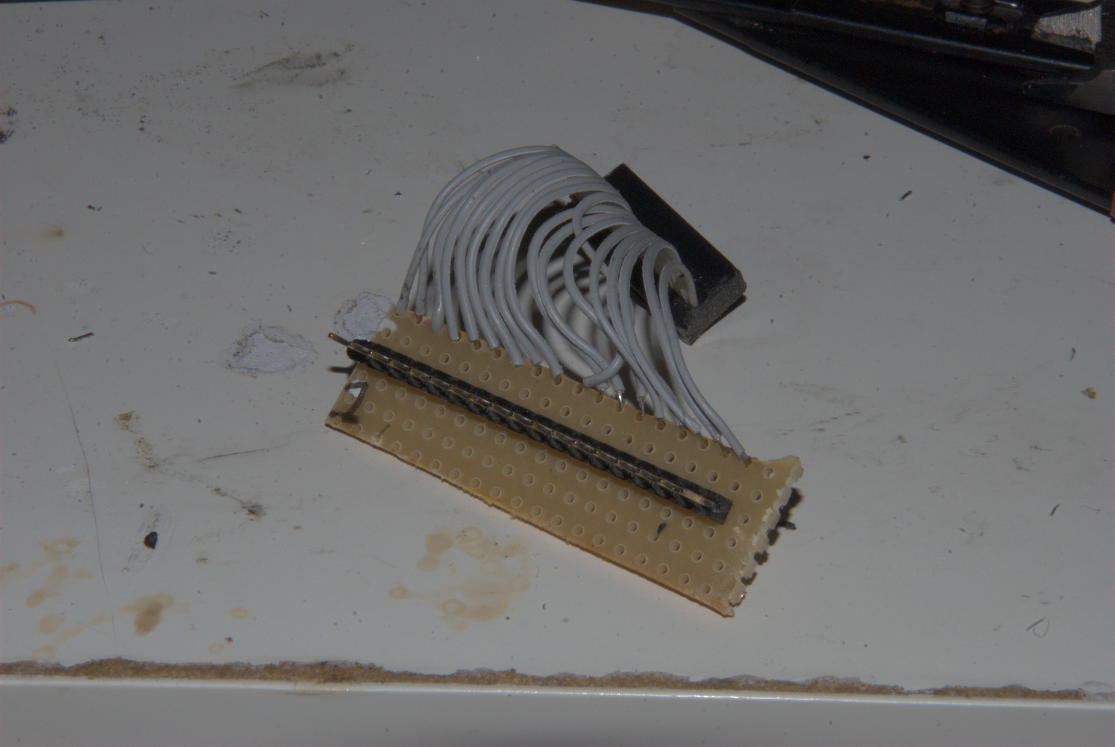
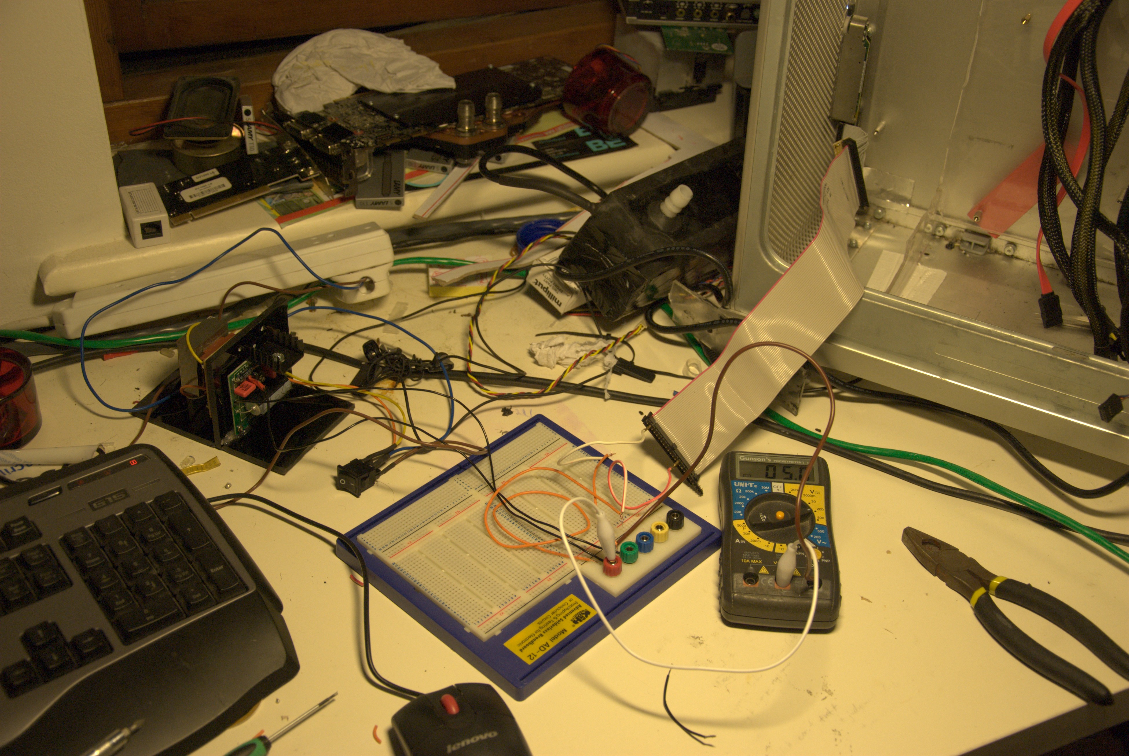
Then I had to do the painstaking work of testing each pin, and seeing what it did on the front panel, in order to make a pinout for the front panel. Done on my rather messy test bench:
By the end of it, we had working power light, power switch, USB and audio headphone jack. I did not try to get the firewire port working, as I had little need for a front panel mount FW connector.
Fifth stage: Front fans
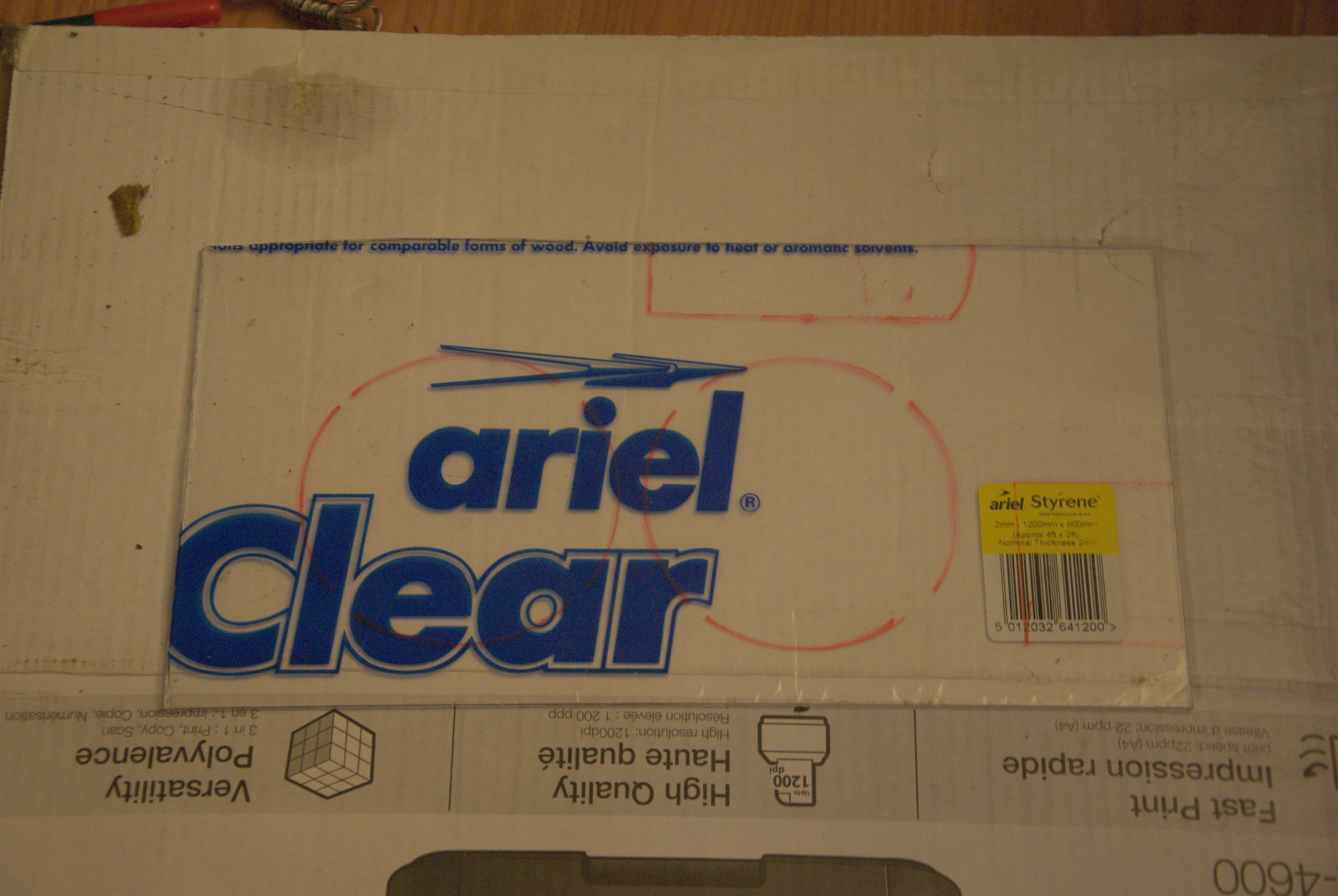
The plan is to mount two fans in front of the radiator, to feed cold air in. However this has to be done without changing the external case. So the plan is to make a flange to mount the fans internally. To start with, we marked and cut out some 3mm acrylic to fit the front of the case, like so:
We then marked out where we need to cut to clear the front panel, as well as the fans themselves. We used transparent acrylic because it made it much easier to mark out mounting holes and openings for the fans.
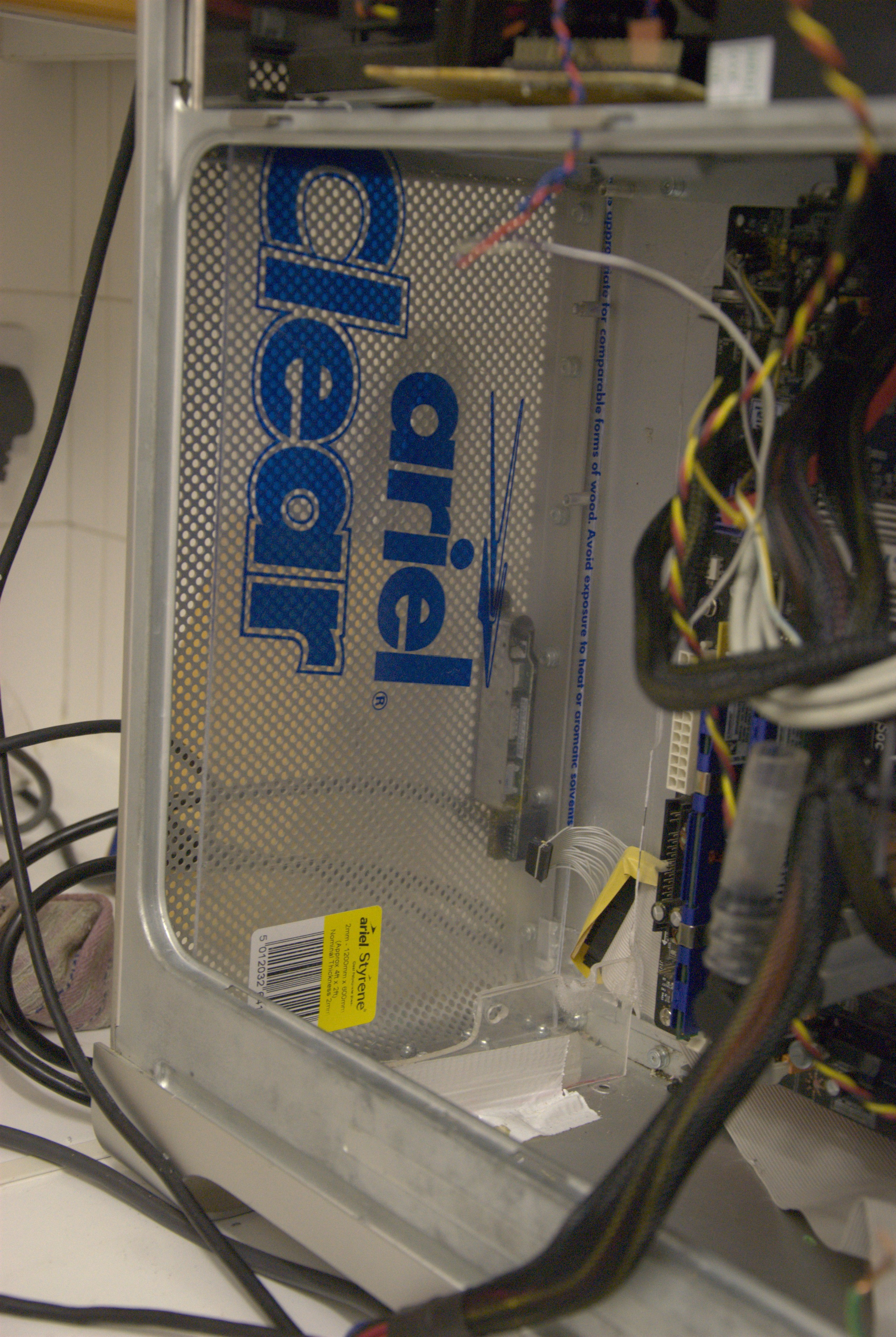
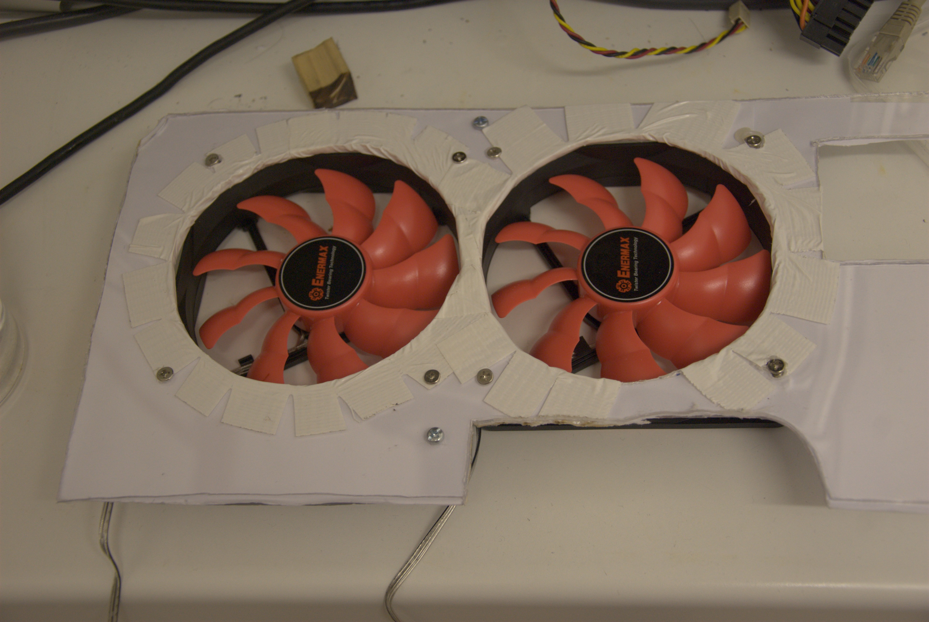
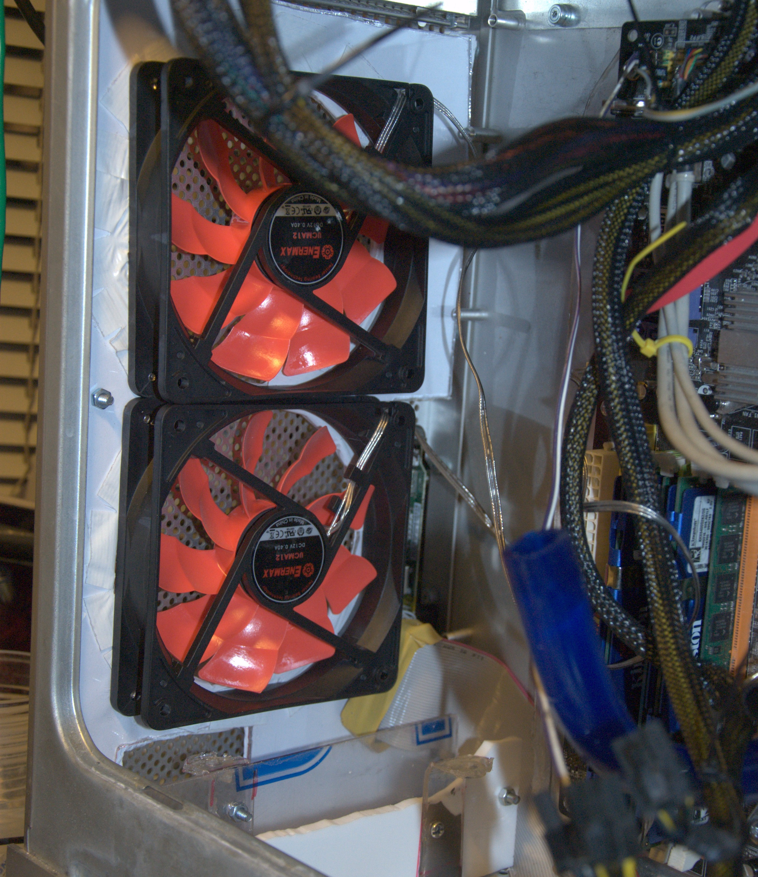
Then we cut out the marked areas using a dremel and hand file. We were unable to make the holes fully round and smooth so the rough edges were filled in with white duct tape. Once done two 120mm fans were fitted. I went with Enermax silent fans, to keep the noise down as much as possible. We also put a white piece of paper behind the clear acrylic, as this then hides the case insides through the grill.
And here it is installed. First the fans alone installed, and after with the radiator fitted behind. You notice the bleed pipe coming from the top of the radiator, with a one way valve that prevents water going back. I found that when you power off the pump, the liquid would drain out of the radiator via the bleed pipe, filling it with air. The valve prevents this from happening.
Sixth stage: Water pump and tank
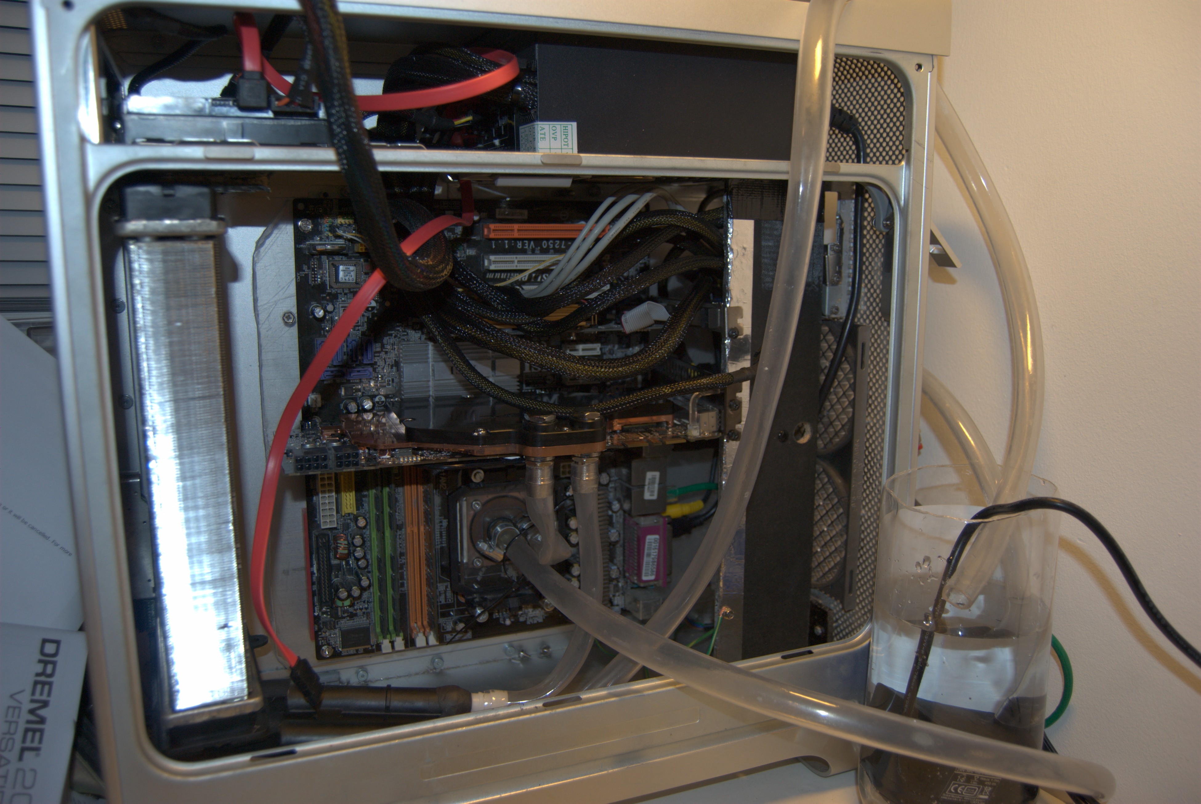
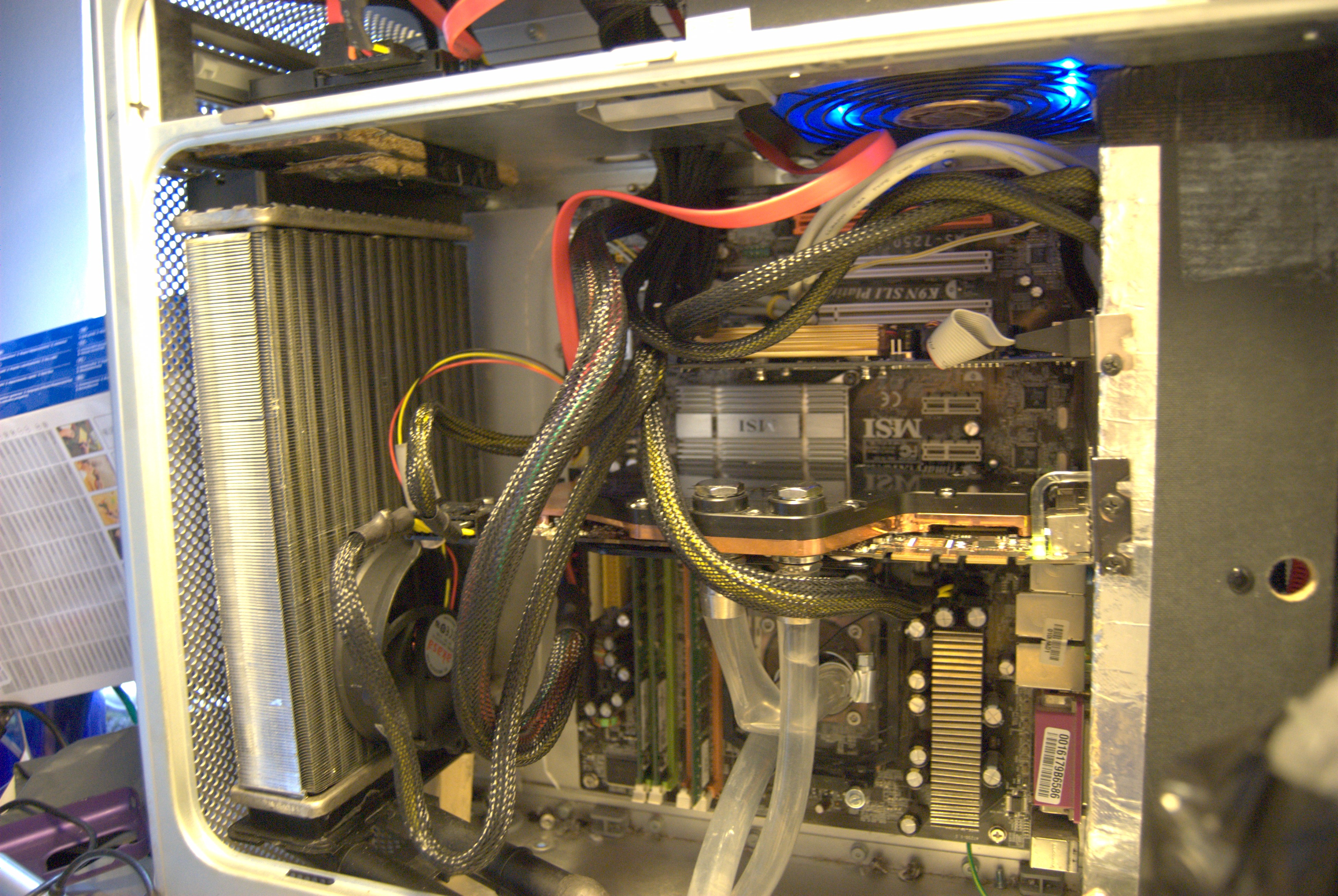
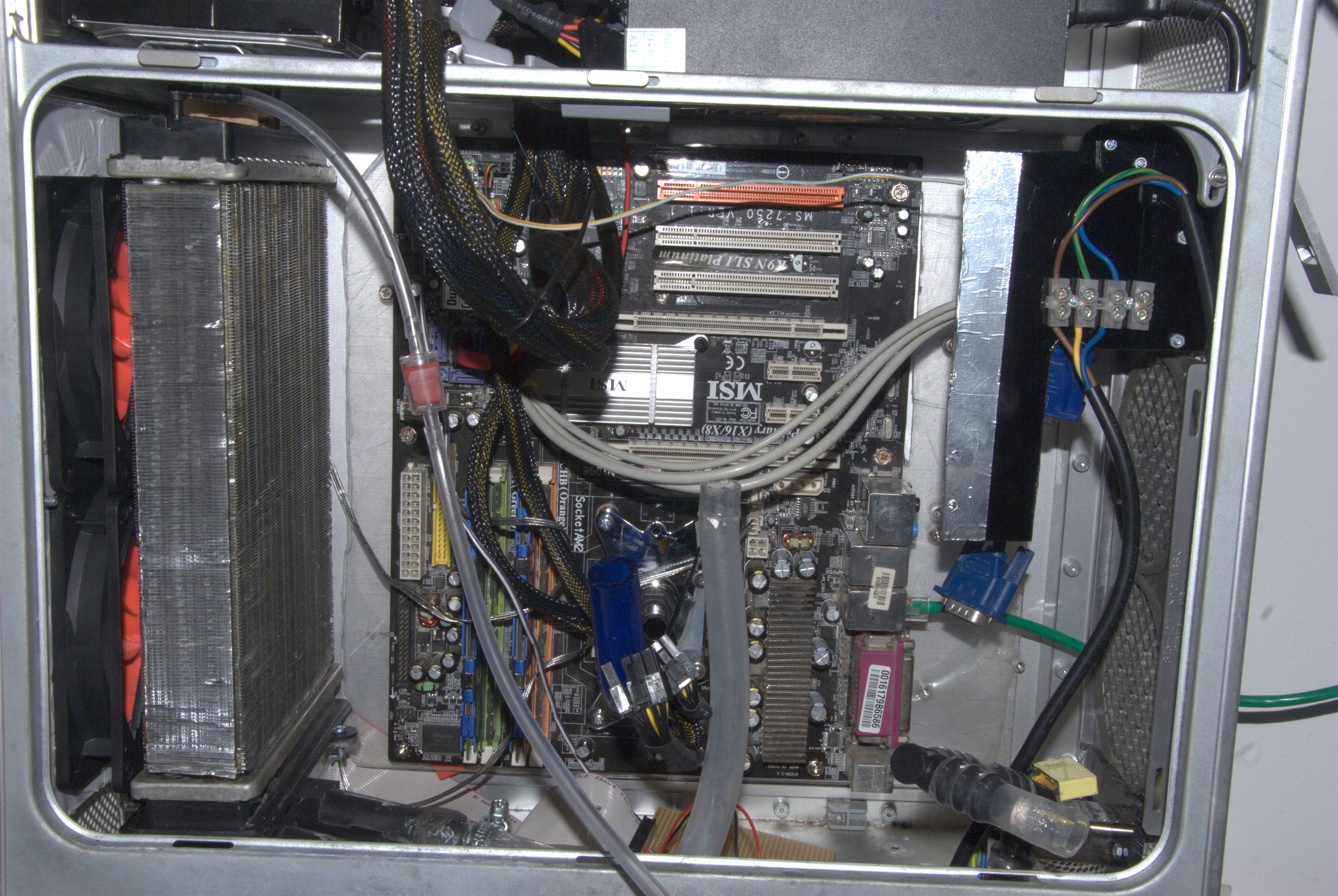
The aquatic pump I bought works by being submerged in the liquid, so we had to build a liquid tank that would also hold the pump and the liquid. This was done with a mixture of acrylic and epoxy putty for sealing. The liquid we decided to use is "Feser One" cooling fluid. The nearly finished product below:
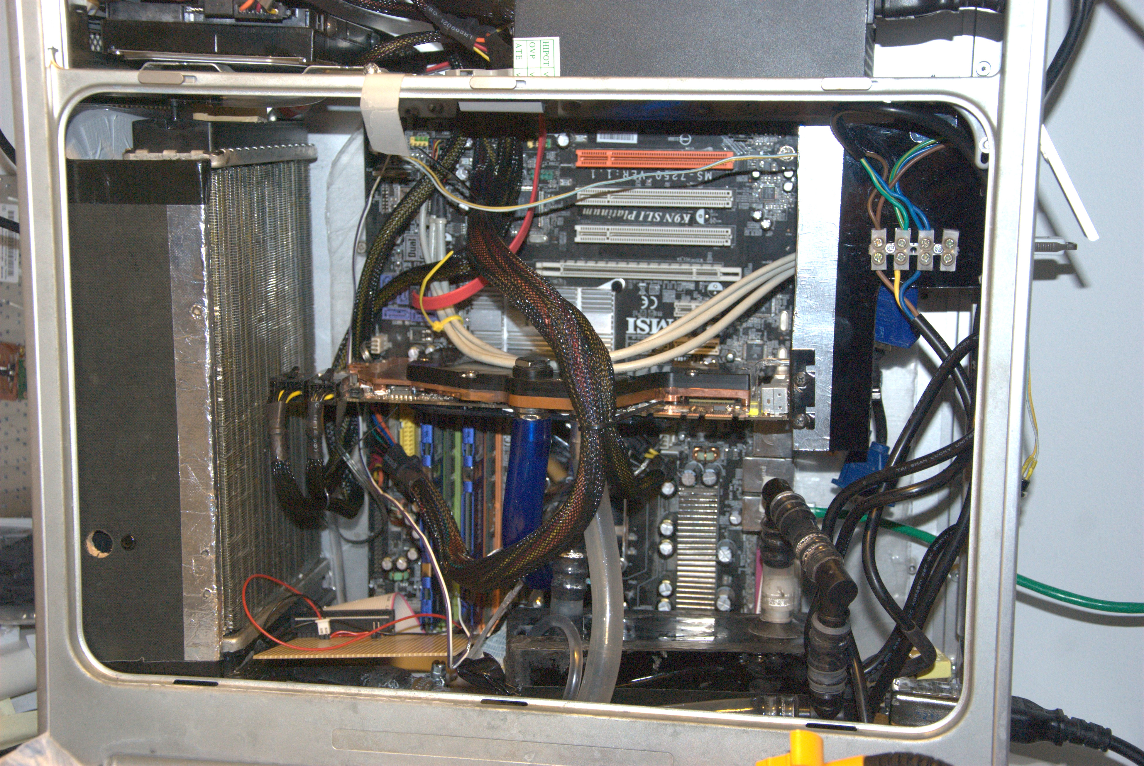
The liquid tank is the rectangle in the lower right of the case. The fan and radiator are shrouded behind the paper composite panel (which originally was used for mounting PCI cards), while we once again made a PCI mount out of acrylic. We covered it with aluminium tape which we earthed, so each card is properly grounded.
The PSU is placed at the top as we discussed earlier but the original power socket is still at the bottom. Thankfully in addition to being 4cm above the floor, there are plenty of holes in the bottom of the case (including the front and rear grids) that there is no way liquid could reach the mains socket in a worst case scenario. The power connector between the PSU and the lower docket meets at the connection block just to the right of the PCI card mount. As acrylic is non conductive this was fine to do, but as mentioned above the aluminium tape is grounded just in case. You don't want to work on the internals of this setup while it is plugged into the mains.
The kinked pipe was replaced with some proper "liquid cooling" pipe that I had bought. It has a thicker wall, making it harder to bend but it does not seem to kink, which is good. We also used 90 degree joints for the other side, which is the return pipe from the radiator to the tank.
The Circuit board in the lower left interfaces between the front panel and the motherboard. For now only the switch and the LED, but as all the pins have been brought to the stripboard, we can in future add whatever extras we may want. At the top-left is our hard drive. Unfortunately lack of space precluded putting it anywhere else, which also means we cannot fit a CD-ROM drive in its original location.
And with that the system is up and running. Temperatures so far look nice a cold, even when running BOINC@Home at full pelt with CUDA and 100% CPU usage the temps never exceed 67C, which is much better than the 100C+ temps I would see on the nvidia temperature before.
Now just to see how it works going forward :-)


